10 GHz evanescent mode filter
Mar 3, 2024
I need a couple of 10 GHz bandpass filters for a down-converter to test my 10 GHz station and decided to build a evanescent mode circular waveguide filter. Evanescent mode filters work below waveguide cutoff frequency and in order to famliarise myself with their properties I started by modelling 2nd and 3rd order filters in CST Studio using designs by K5TRA and G4JNT. I also found a useful paper by Sam Mandev that runs through an example of determining distances between tuning screws.
Models
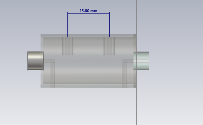
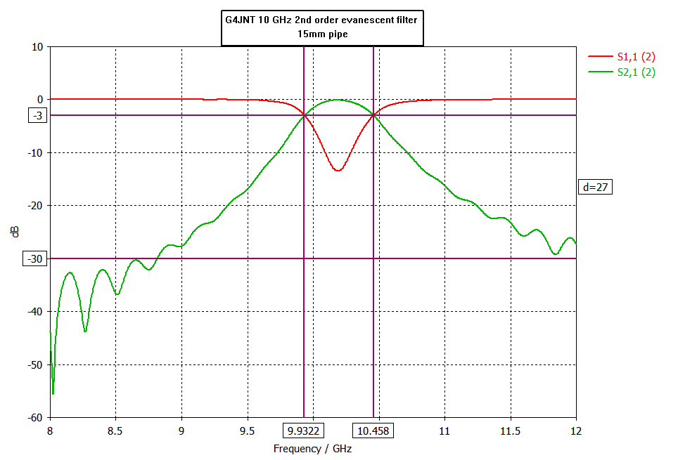
The G4JNT 10 GHz 2nd order filter uses WR42 waveguide and when I modelled it using circular waveguide (15mm o/d pipe) I got very similar results. Tuning screws are M3 and spacing between the tuning screws is 13mm. The screws are 6mm away from the SMA probes which are attached to the inside walls of the circular waveguide. Tuning screw depth is close to 5mm.
I then modelled several 5th order designs using dimensions from K5TRA and calculations from the Mandev paper. The best model and results are shown below. Once again the M3 tuning screws are 6mm away from the SMA probes and the tuning screw depth is close to 5mm. I also included M1.6 tuning screws above each SMA probe and although this flattened the response curve the return loss is not very good.
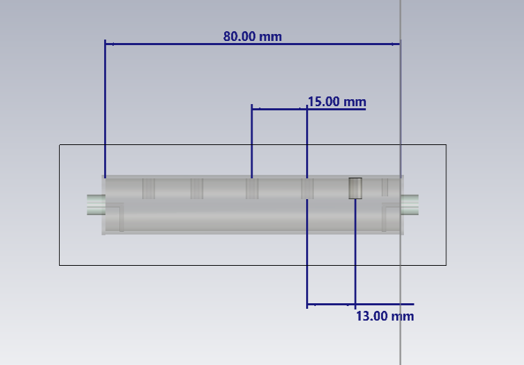
5th order filter
I built a 5th order filter using a 80mm length of 15mm o/d copper pipe. The SMA connectors are screwed into the end caps and a thin wire soldered between the probe and pipe wall. This limits how close the end cap can be inserted and the spacing to the first tuning screw is around 11mm instead of 6mm. Overall length of the circular waveguide with the end caps in place is 90mm. This filter did not include any tuning screws for the SMA probes.
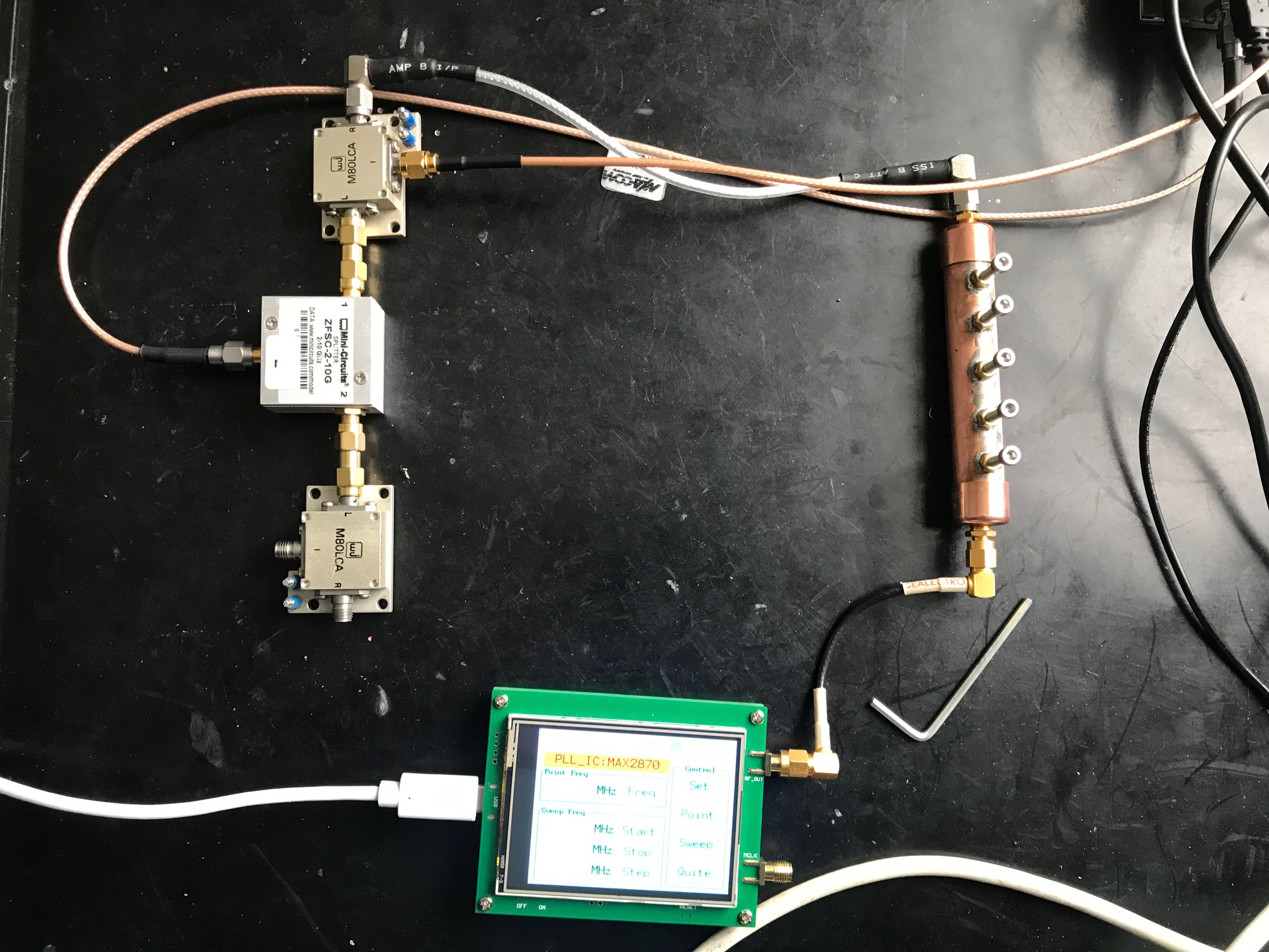
Test setup
I have a Viavi JD785 analyser which covers 5 MHz to 6 GHz in VNA mode. By connecting it to two mixers and injecting a LO signal at 9936 MHz I measured the response of the filter by down converting to 432 MHz. This method introduces losses and some inaccuracies, and is not the same as using an analyser at 10 GHz but seems to be OK for simple alignment tasks and relative measurements.
Tuning
For a 10 GHz signal source I either up-convert 432 MHz from the Viavi RF out port or use the third harmonic of 3456 MHz from a MAX2870 OLED signal generator. To tune the filter I removed screws 2 and 4, applied the 10 GHz test signal and adjusted screws 1, 3 and 5 for maximum output on the spectrum analyser. Screws 1, 3 and 5 were then locked off. Changing to 2-port scalar VNA mode and using a 5 Mhz - 1GHz span I then inserted screw 2 and adjusted for the best response curve centred around 432 MHz. This step was repeated for screw 4.
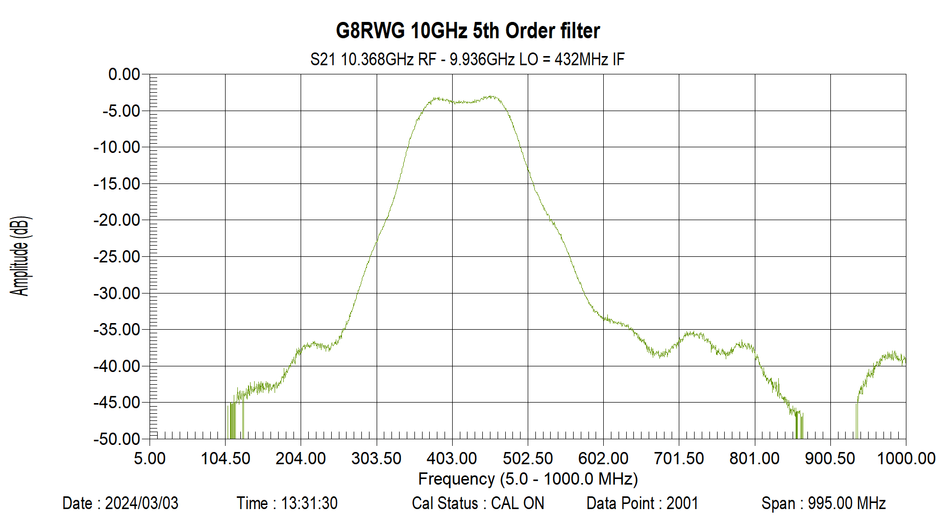
As a first attempt the filter appears to work well but the 130 MHz 3dB bandwidth is narrower than the 500 MHz of the model. Insertion loss is around 3dB. I plan to build a couple more and will look at aligning the SMA probes in the same plane as the tuning screws.