10 GHz dual-mode feedhorn - simulation
Jan 22, 2024
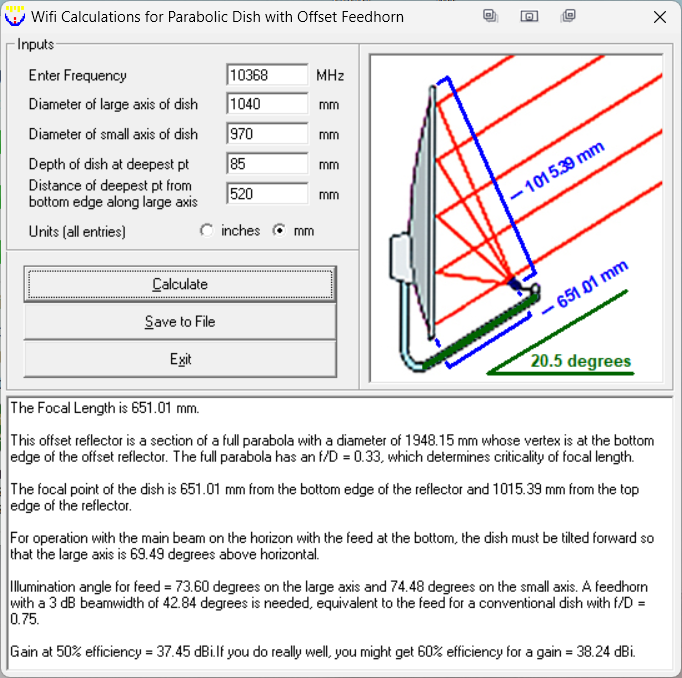
I recently salvaged a 1m offset dish that I’m planning to use on 10 GHz and need to build a suitable feed. To determine the dish properties and parameters for a suitable feedhorn I used the Wifi calculations option in Parabola Calculator version 2.0 (same code as W1GHZ’s HDL_ANT program).
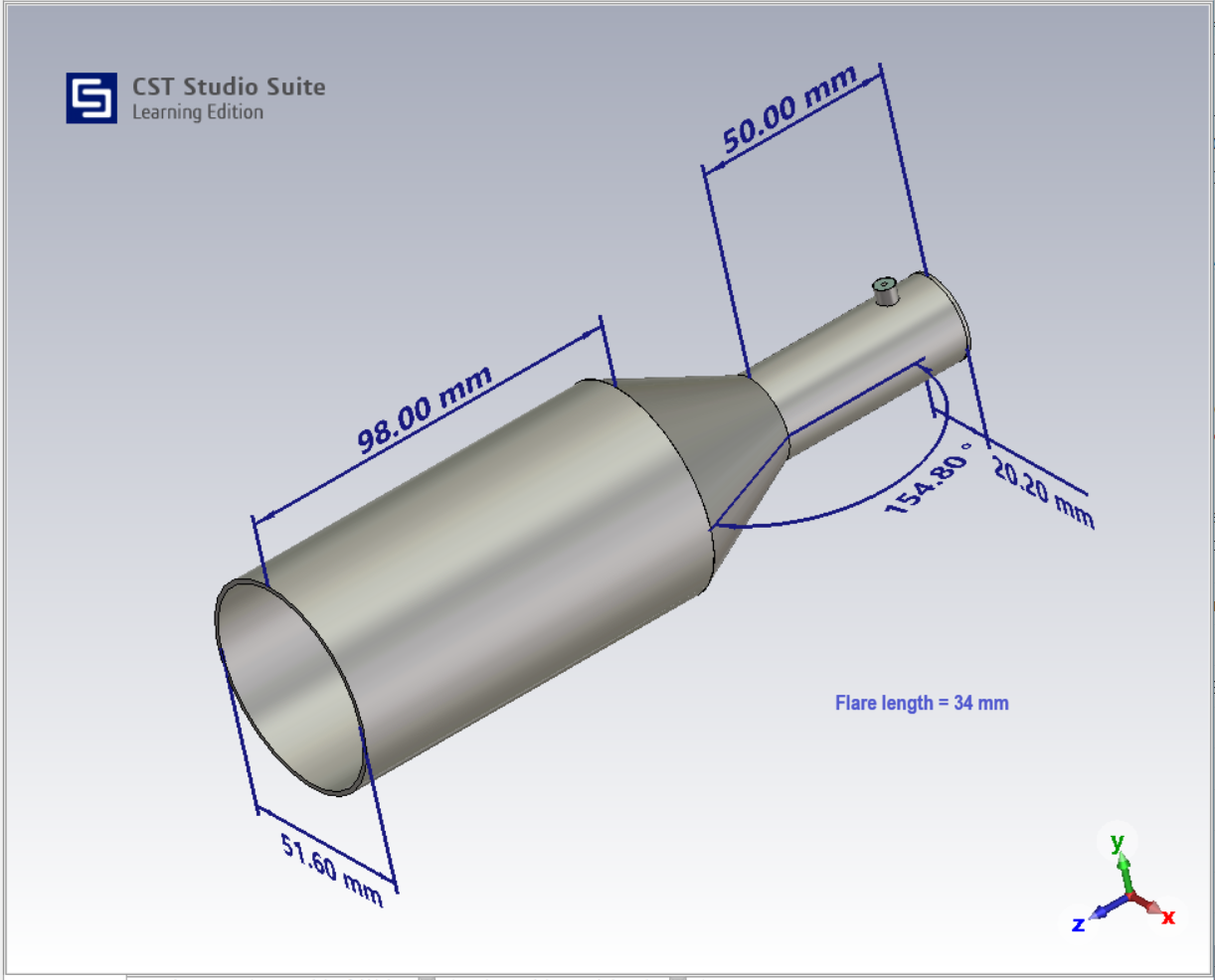
Dual-mode feedhorns are frequently used for offset dishes because of their performance. The W2IMU Horn Design and Template option in HDL_ANT generated the following dimensions for a dish with a f/D = 0.75 at 10.368 GHz.
- Input circular waveguide diameter 20 mm
- Aperture diameter 50.963 mm
- Flare half-angle 25.30 degrees
- Output phasing section length 98.007 mm
The dimensions of readily available 22 mm od. and 54 mm od. copper pipe look suitable, with the flare section cut from 1.2mm thick copper sheet.
Modelling and simulation
As a newcomer to the microwave bands I decided to model the feedhorn to see how close this design would be compared to examples in Chapter 6 - W1GHZ Microwave Antenna Book. I used CST Studio Suite 2023 - Learning Edition, available as a free download for personal/educational use, from Simulia - Dassault Systèmes.
Two models were built, one for the feedhorn and one for a circular waveguide coaxial adapter. Simulations were run for each model separately between 8 GHz and 12 GHz, and then for the combined feedhorn/waveguide model.
| Parameter | Simulated Results | Notes |
|---|---|---|
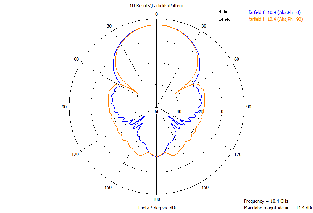
| Gain @ 10.4 GHz | 14.4 dBi | |
| 3 dB beamwidth @ 10.4 GHz | H-field 37.2 deg. E-field 35.6 deg. | Optimum is 42.84 deg. |
| 10 dB beamwidth @ 10.4 GHz | H-field 70 deg. E-Field 68 deg. | |
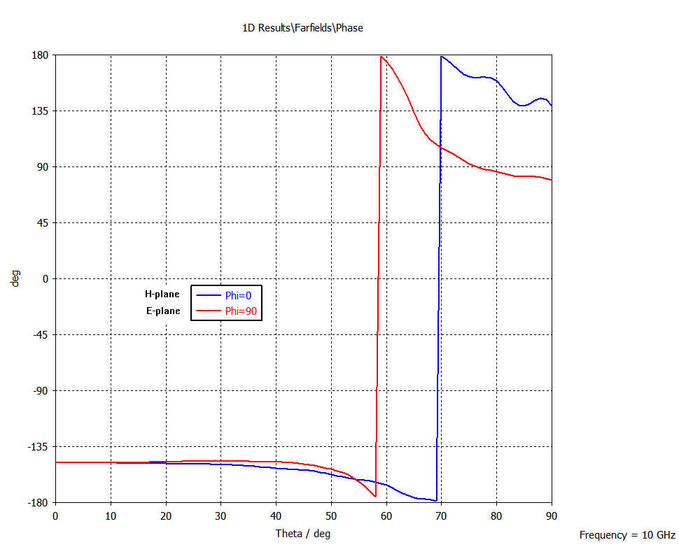
| Phase centre | 0.7 λ in front of aperture | Good phase correlation in H-plane and E-plane |
| Input port impedance | 57 Ω | |
| S11 Return loss | -18 dB @ 9.5 GHz | -23 dB @ 10.4 GHz on separate model |
| VSWR | 2:1 | 1.15:1 on separate model |
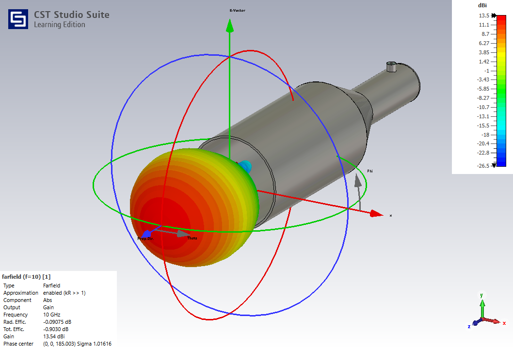
Getting to grips with CST Studio Suite has been a steep learning curve but with the assistance of comprehensive on-line help and several videos I was able to build and test some simple examples before attempting this design. I’m confident that the feedhorn model and simulation above are a good representation as the results are close to similar dual-mode feedhorns described in W1GHZ’s publications and elsewhere.
It took a while to figure out how to plot phase in the E and H planes around the phase centre. The phase difference is minimal between 0 deg. and 50 deg. and similar to W1GHZ’s examples, but I’m sure about the phase shift between 60 deg. and 70 deg.
The input port of the circular waveguide coaxial adapter is quite crude and I plan to improve this by building a better SMA connector model. Testing different probe lengths and backshort distances produced the expected results so I’m happy that the basic adapter model is correct.
I would also like to carry out some dish illumination calculations using DF3GJ’s software at some stage.
References
- Parabola Calculator version 2.0
- Optimized Dual-mode Feedhorns, Paul Wade W1GHZ, 2006
- Designing, Building and Testing Feeds for Offset Dishes, Charlie Suckling, DL3WDG - Dubus 4/2023
- A dual mode horn for 10 GHz using standard copper pipe fittings, Peter Day G3PHO
- Performance of Parabolic Dish Antennas Illuminated by Various Feeds, Joachim Köppen DF3GJ, 2020