10 GHz station overview
Feb 14, 2024
I’ve spent the last few weeks putting together some equipment for a small 10GHz station using a mixture of pre-built and homemade modules. The block diagram shows the main components of the system.
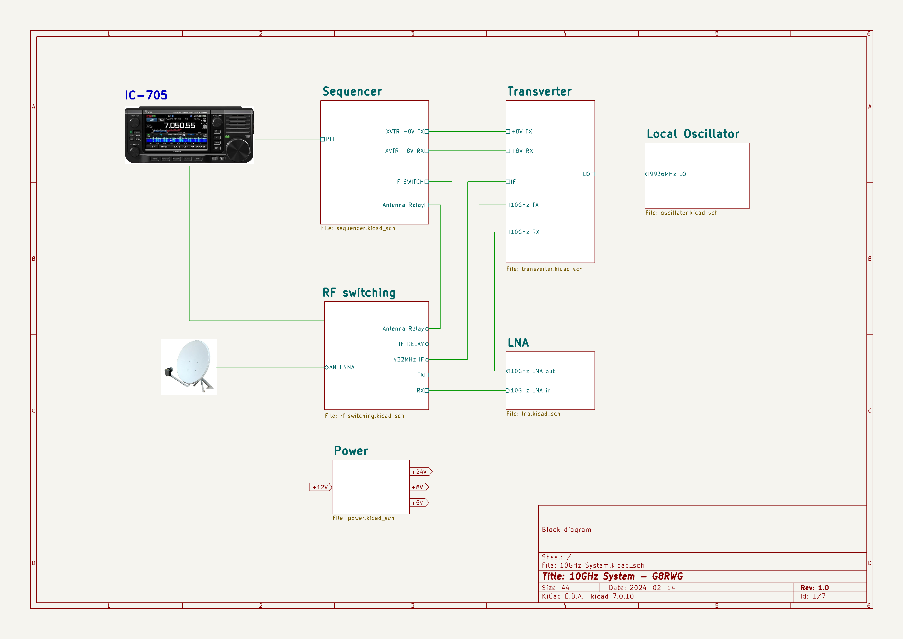
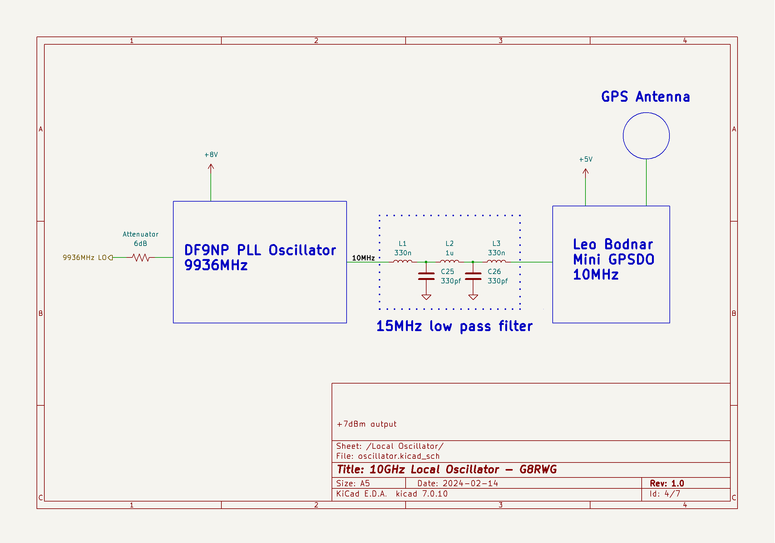
The core of the system is a simple transverter designed by W1GHZ and a DF9NP PLL local oscillator board running at 9936MHz for the 432MHz IF. It’s probably overkill but I decided to repurpose the 4 channel Ardunio sequencer I was planning to use for the 2m EME station. It provides a lot of flexibility and is ideal for handling different relay voltages.
With the exception of the LNA, which I’m still building, all the modules have been tested on the bench. My simple test gear consists of a home made AD8317 noise meter, a MAX2870 signal generator, a satellite LNB and SDR. I’ve found that by setting the MAX2870 to 1152MHz the 9th harmonic will generate a reasonable signal at 10GHz for aligning pipe cap filters and testing receive gain blocks.
Now I just need a couple of dry days to hook up everything outside and do some further testing.
KiCad
KiCad is a powerful, open source, electronic design automation (EDA) tool that I use for schematics and PCB design. Up until recently I had design files located in different places on a network drive. Now, where it makes sense, I use the hierarchical schematics feature in KiCad. I set up the root sheet as a block diagram and add separate subsheets for each main module along with a combination of labels and pins for interconnections. Clicking through on a subsheet in the Kicad schematic editor brings up the detail - for example the local oscillator shown below. It’s a great way of organising a project and allows modules to be easily changed and modified.