Feeding XPOL Yagis for RHCP
Nov 8, 2023
In May 2021 I changed the feed arrangement on my 144MHz XPOL EME array to transmit right hand circular polarisation (RHCP). Circular polarisation (CP) is frequently used for EME on 1296MHz and above, it’s not so common on 144MHz or 432MHz. The main advantage of CP compared with horizontal or vertical polarisation is that losses due to Faraday rotation are minimised but there is a -3dB penalty when one station is using CP and the other is using linear polarisation.
Offset between dipoles
Some XPOL Yagis are designed with a 1/4 wave spacing (90 deg. phase shift) between horizontal and vertical elements. For these Yagis, feeding both dipoles with equal lengths of coax will generate circular polarisation.
On Yagis where the spacing is not 1/4 wave the delay required is introduced by using an extra length of coax to feed one of the dipoles. http://dg7ybn.de/Building/xpol.htm#Offset_Planes
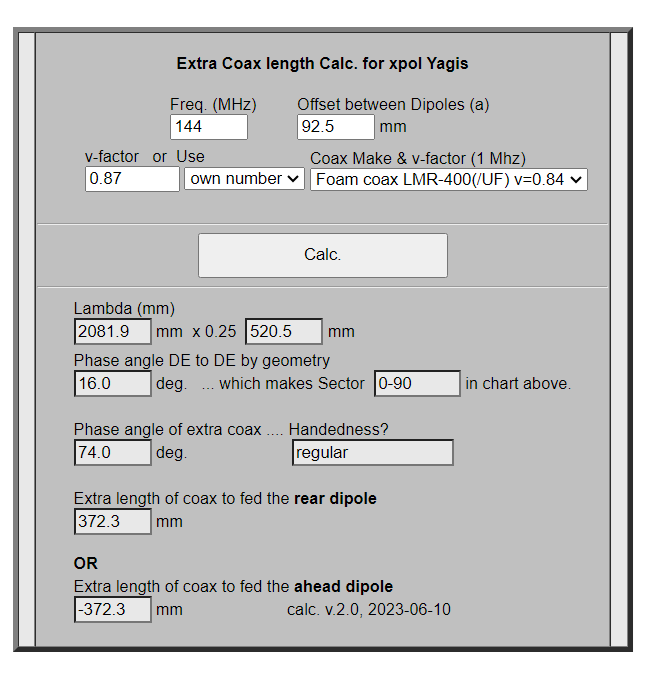
The spacing between the horizontal and vertical dipoles on the DG7YBN XPOL Yagis I built is 92.5mm. This is 16 deg. at 144MHz therefore I need a 74 deg. delay to feed one of the dipoles.
RHCP arrangement
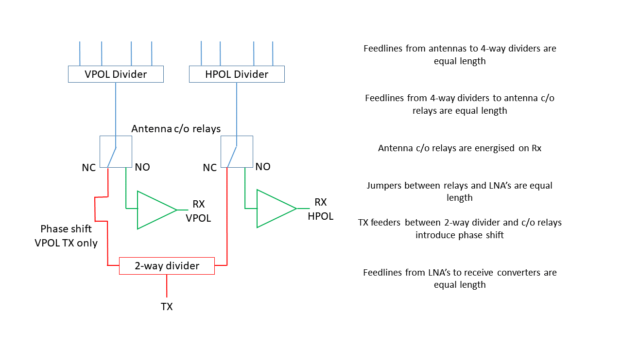
The transmit signal is split using a 2-way power divider allowing the vertical antennas to be fed with a delay of 74 deg. (90 - 16) compared to the horizontal antennas.
All feeder lines are measured with a VNA to make sure that where required, they are the same electrical length to minimise phase differences. This is especially important for the receive part of the system that uses the adaptive polarization capability of Linrad and MAP65.
DG7YBN Calculator
DG7YBN provides a useful Coax Length Calculator, to work out the extra length of coax required for feeding the other dipole for circular polarisation.
I’m using LMR600 as the transmit feeder between the 2-way divider and the antenna changeover relays. For 74 deg. delay an extra 372.3 mm of coax will be required.
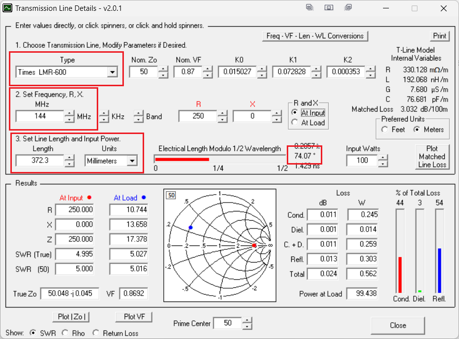
TL Details
To verify this approach, I posted a message to the RSGB-Workshop Groups.io forum and G4SWX suggested using AC6LA’s Transmission Line Details utility program to calculate the line lengths.
Building the feed lines
The horizontal transmit feeder was cut to 1020mm. This was long enough to route the feeder from one output port on the 2-way divider to the antenna changeover relay in the masthead control box with a nice bend radius. The vertical transmit feeder would need to be 372.3mm longer and was cut to 1395mm. Both feeders were terminated with 7-16 DIN connectors at one end and left open circuit at the other.
Using a Viavi JD785 analyser I ran a 1 Port Phase scan to calculate the phase difference between the two cables. It came out at 75.5 deg. very close to the TL Details calculation of 74.6 deg. I trimmed the vertical feed to 1390mm which gave me a 74.5 deg. difference required (TL Details 73.61 deg.)
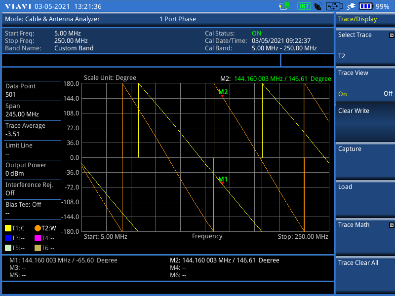
| HPOL | VPOL | |
|---|---|---|
| Physical length | 1020mm | 1390mm |
| Phase @ 144.160MHz | -65 deg. | 146 deg. |
| Unwrap | -65 mod 360 = 295 | 146 mod 360 = 146 |
| Difference | 295 - 146 = 149 | |
| Divide by 2 for electrical length | 149/2 = 74.5 |
After terminating the open ends with 7-16 DIN connectors the measurements were re-run; the phase difference between the two cables remained the same.
Modeling with AutoEZ/EZNEC
Using AutoEZ/EZNEC I added the XPOL feedline arrangement to the antenna model for a single DG7YBN 12 element XPOL Yagi to see what the effect would be on the phase of the currents.
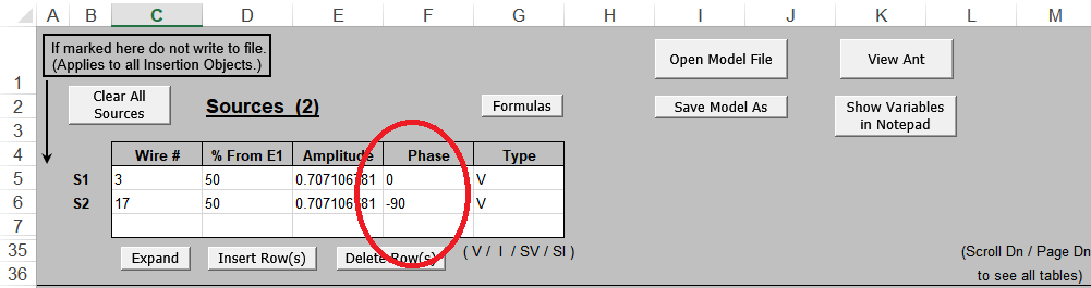
In the first example the HPOL and VPOL antennas are driven with seperate sources, 90 deg. out of phase. As expected this results in a 90 deg. phase difference between currents on the HPOL and VPOL elements.
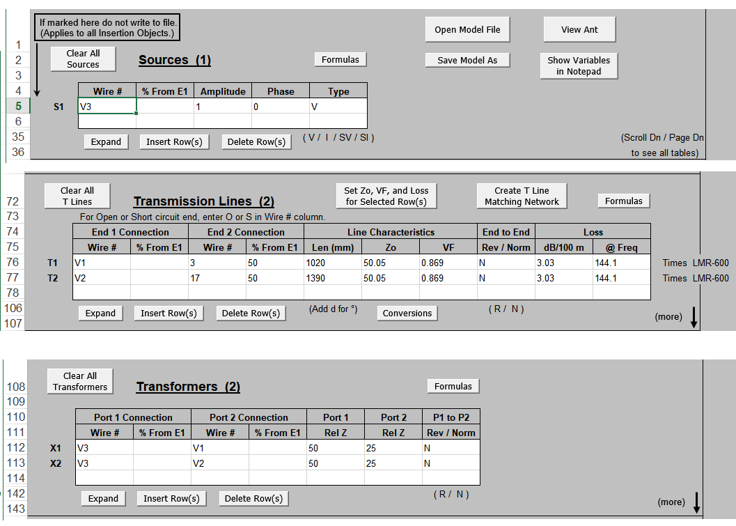
To model the XPOL feedline arrangement, the lines are setup as two Transmission Lines, V1 and V2, with lengths of 1020mm and 1390mm using LMR600 cable properties. These lines are connected to centre of the respective dipoles. The Transformers section defines a 2-way divider and the model is driven through a source at the input port V3.
This results in a 71 deg. phase difference between the currents on the HPOL and VPOL elements, quite close to the 74 deg. calculated above.
Here is an animation showing how the current phase difference varies as the length of the VPOL feedline is increased from 1190mm to 1490mm in 50mm steps.
References
DG7YBN XPOL Yagis - http://dg7ybn.de/Building/xpol.htm
SV1BSX Antenna Circular Polarization - https://www.qsl.net/sv1bsx/antenna-pol/polarization.html
AC6LA Antenna Modeling Software and Other Utility Programs - https://ac6la.com/