AD8317 Noise meter - Part 1
Jan 16, 2024
Background
Recently I’ve started experimenting on 10GHz and as I have no test equipment above 6GHz I decided to build a noise meter that would cover 10GHz as well as possible IF’s of 432MHz and 910MHz.
There are several noise meter designs using the AD8307 (DC - 500MHz) and AD8313 (0.1GHz - 2.5GHz) rf log detector devices and I’ve been using two AD8313 devices in an Arduino based RF power meter since 2021.
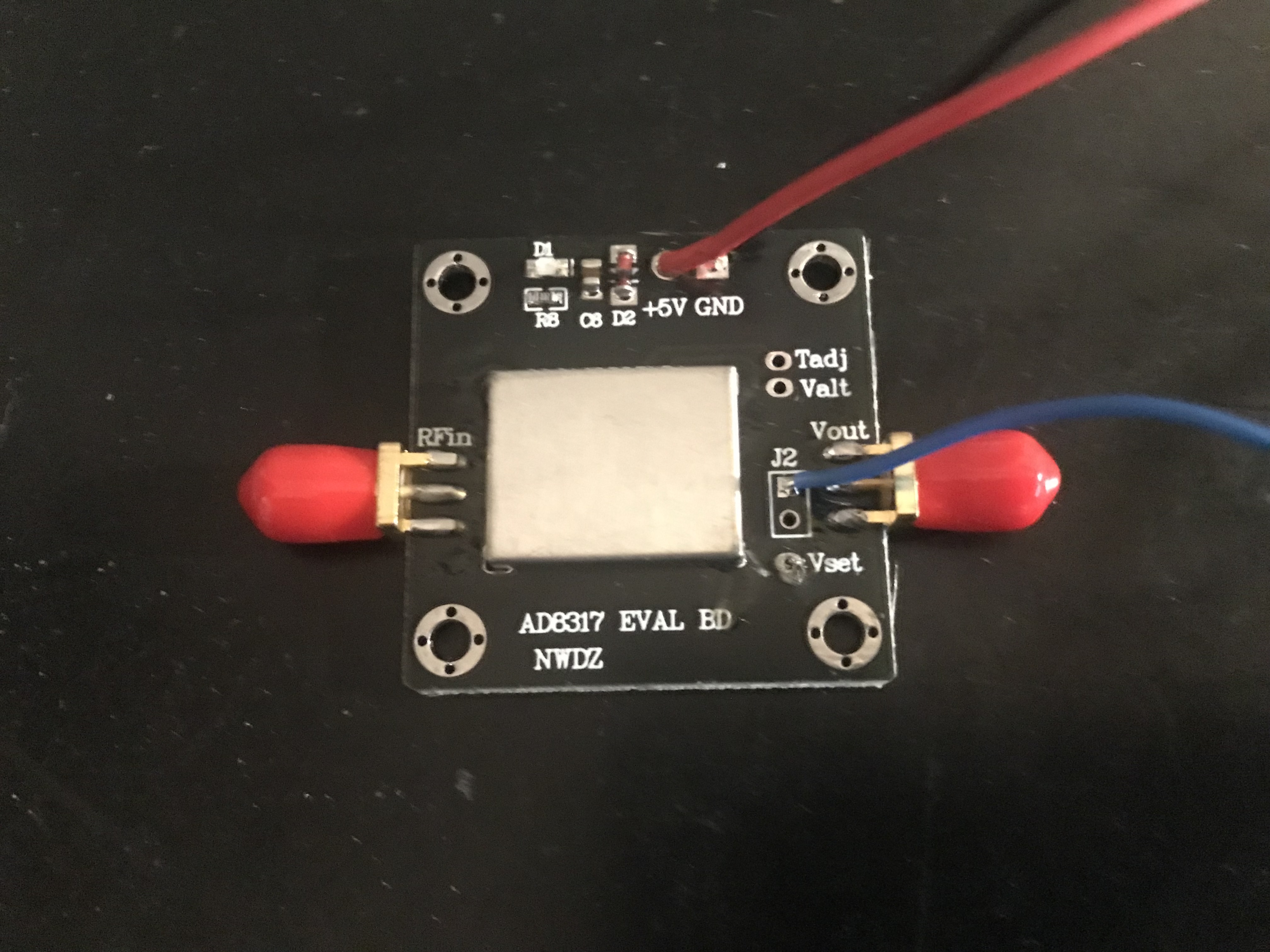
Although it has a reduced dynamic range of 30dB at 10GHz the AD8317 device looks promising and I ordered a module from eBay.
Design
The VK3NX, DB6NT and PA0PLY noise meters using AD8307 and AD8313 devices are similar. Op-amp stages are used to multiply the output of the rf log detector and a bank of resistors switches the output for the panel meter to indicate different power levels. The VK3NX and DB6NT designs include amplifiers ahead of the AD8307 to get signals up to the levels required. Full details are in the references below.
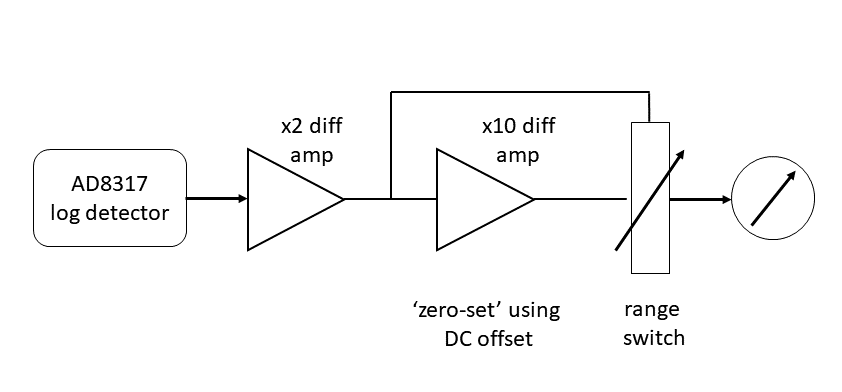
The AD8317 has negative slope, the output voltage decreases as rf input increases, this requires a slightly different design compared to noise meters based on the AD8307 and AD8313 devices. The first op-amp stage is configured as a x2 differential amplifier. The output voltage of the diff amp ranges from 0V to around 2.5V, corresponding to a rf input between -55dBm and 0dBm. This ‘raw’ output is fed directly to the panel meter and also also drives the second op-amp stage. This second stage is configured as a x10 differential amplifier and has a variable DC offset voltage that allows the meter to be ‘zero-set’ to represent a ’no signal’ or ‘cold sky’ baseline. When the signal level at the log detector increases, for example ‘sun noise’ or a pipecap filter being tuned, the output of the x10 diff amp will increase. By selecting suitable resistors the panel meter can be calibrated to display different power level ranges.
At this stage I haven’t included any amplifiers in front of the AD8317, these will included at a later stage once I have the basic meter working.
Calibration
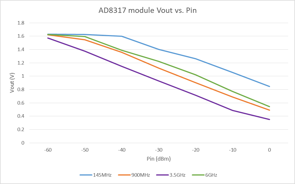
The AD8317 module I’m using has the logarithmic slope set to 22mV/dB. I used the output of a Viavi JD785 at different frequencies to check the slope and dynamic range of the device. Linearity and dynamic range at 1GHz and 3.5GHz is good and as expected drops off at 144MHz and 6GHz.
These calibration steps were then repeated with a breadboard version of the noise meter to determine suitable resistor values for the panel meter. I have used the same ranges as the VK3NX and DB6NT meters; 20dB, 10dB, 2dB, 1dB and 0.5dB.
Construction
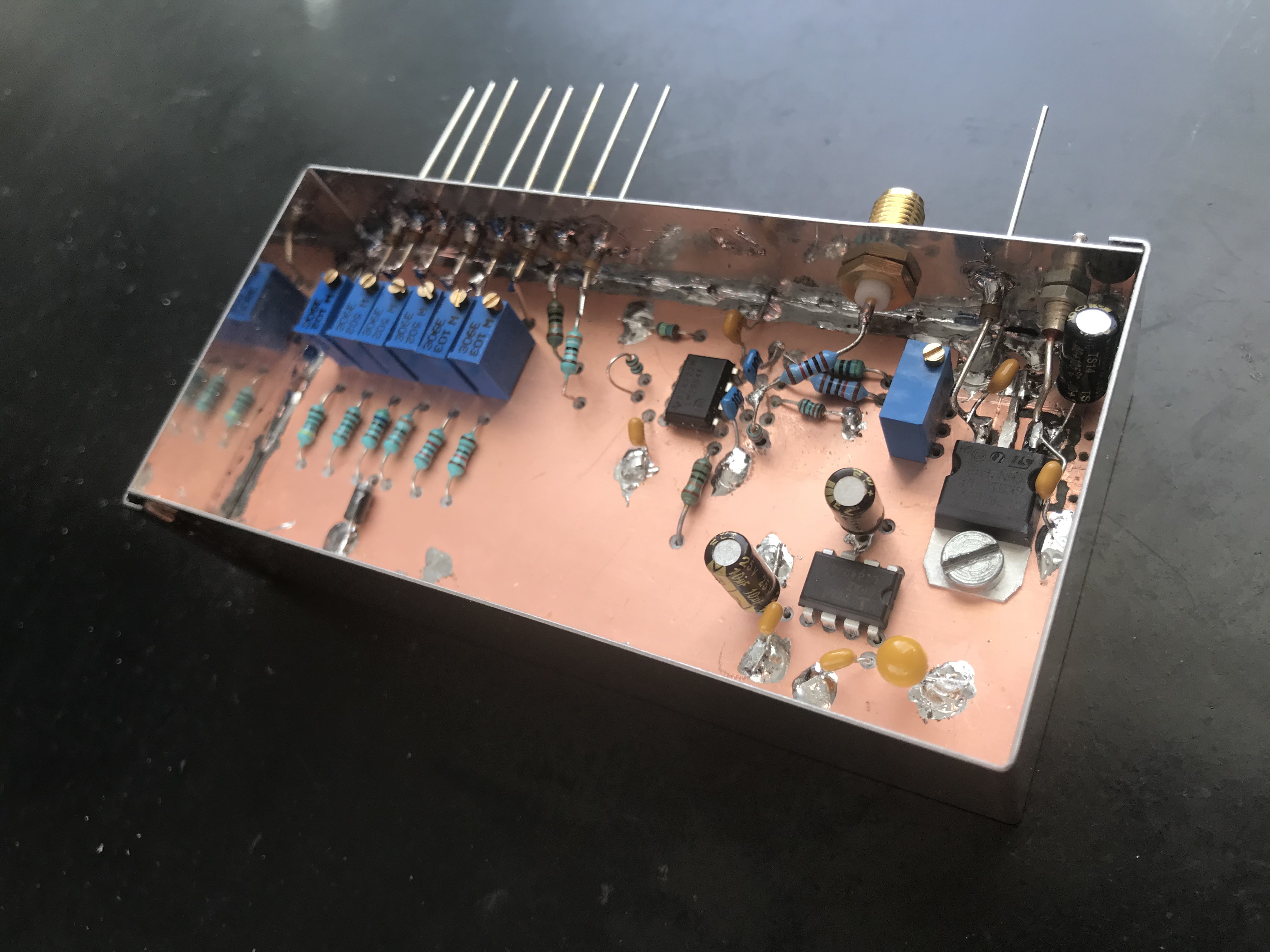
I used a single sided PCB housed in a tinned box for the op-amp stages and resistor bank. When it’s complete, the noise meter will be put in an enclosure with the AD8317 module, panel meter, range switch, zero set pot etc.