RF Power Meter using two AD8313 devices
Apr 30, 2021

Background
In May 2017 I built a simple RF Power Meter using a AD8313 rf power detector module from SV1AFN, an Arduino Nano and a LCD module. The meter was battery powered and it was calibrated for use at 144MHz using the output of my HF to 2m transverter via some variable attenuators. The meter worked well, either with an external attenuator or a directional coupler.
In November 2020 I started experimenting with a ADL5519 dual channel module, also from SV1AFN, so that I could measure forward and reflected power simulataneously. I found it harder to calibrate than the AD8313 and the meter didn’t always give me consistent readings, so I decided to go with two AD8313 devices instead.
I used the articles linked at the bottom of this page to design, build and test these RF power meters.
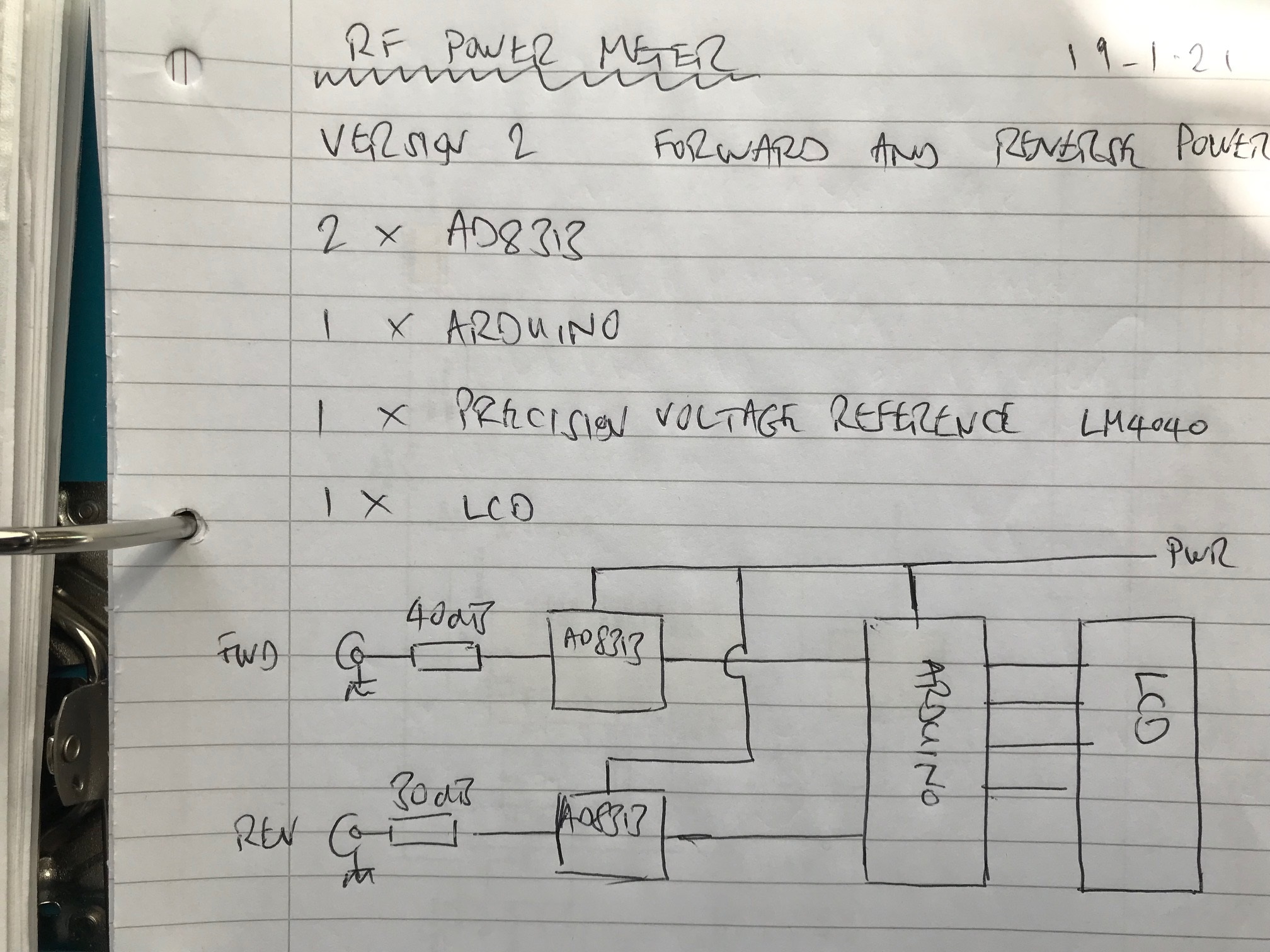
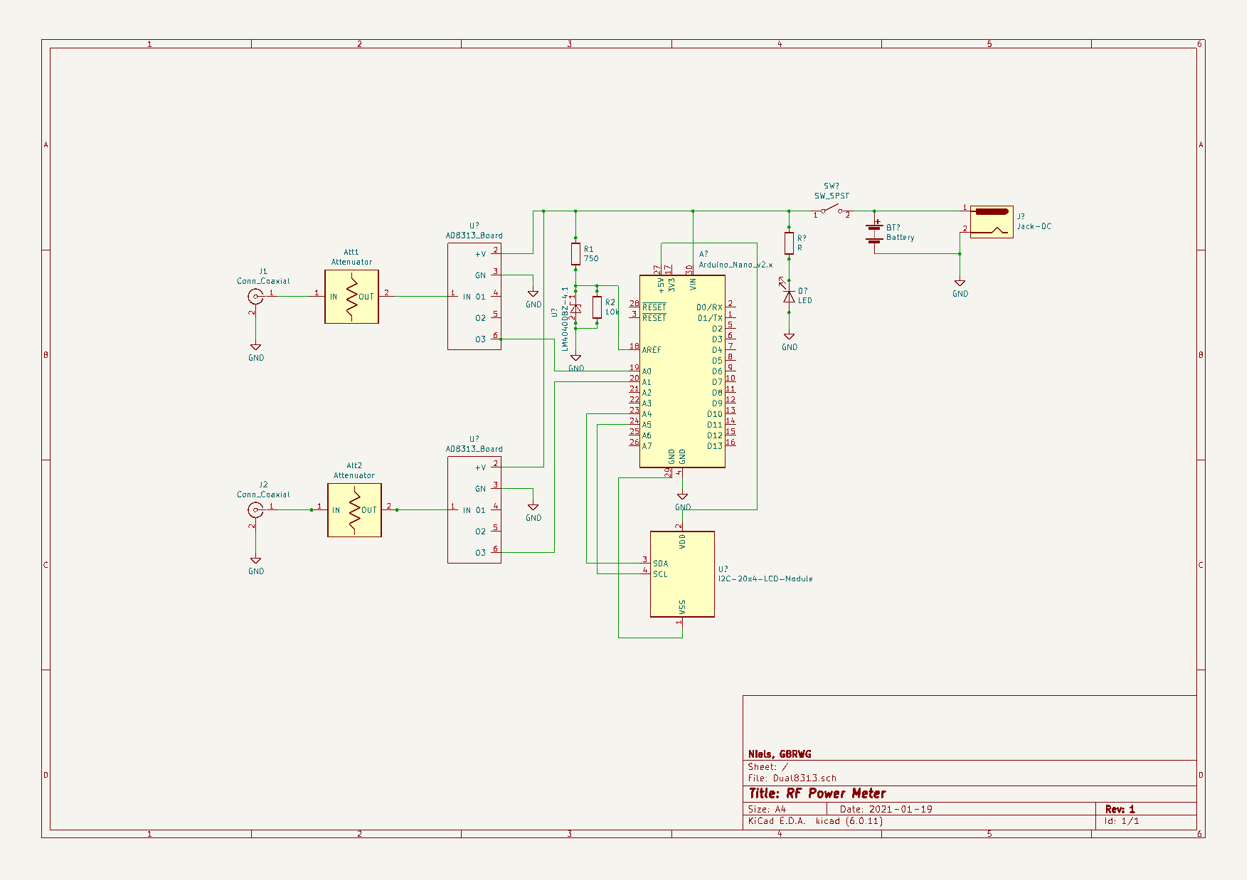
Design
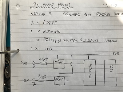

Suitable attenuators are required to keep the rf power detection within the linear range of the AD8313. I use HP SMA type attenuators, Att1 (forward) is 40dB and Att2 (reflected) is 30dB.
Calibration
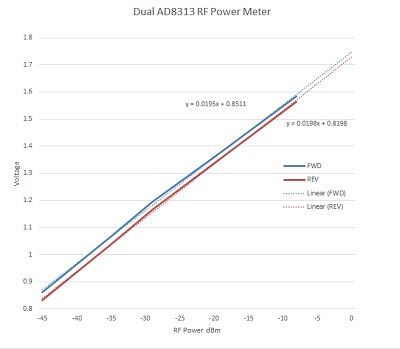
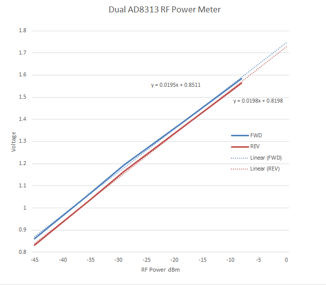
To determine the slope and intercept values of the AD8313 devices at 144MHz, I used the output of my Kuhne TR144 transverter and 2 stepped attenuators. I plotted the AD8313 output voltages for several points between 0dBm and -45dBm and used an Excel spreadsheet to calculate the slope and intercept values. These values are used in the Arduino sketch to calculate the rf power detected.
Arduino sketch
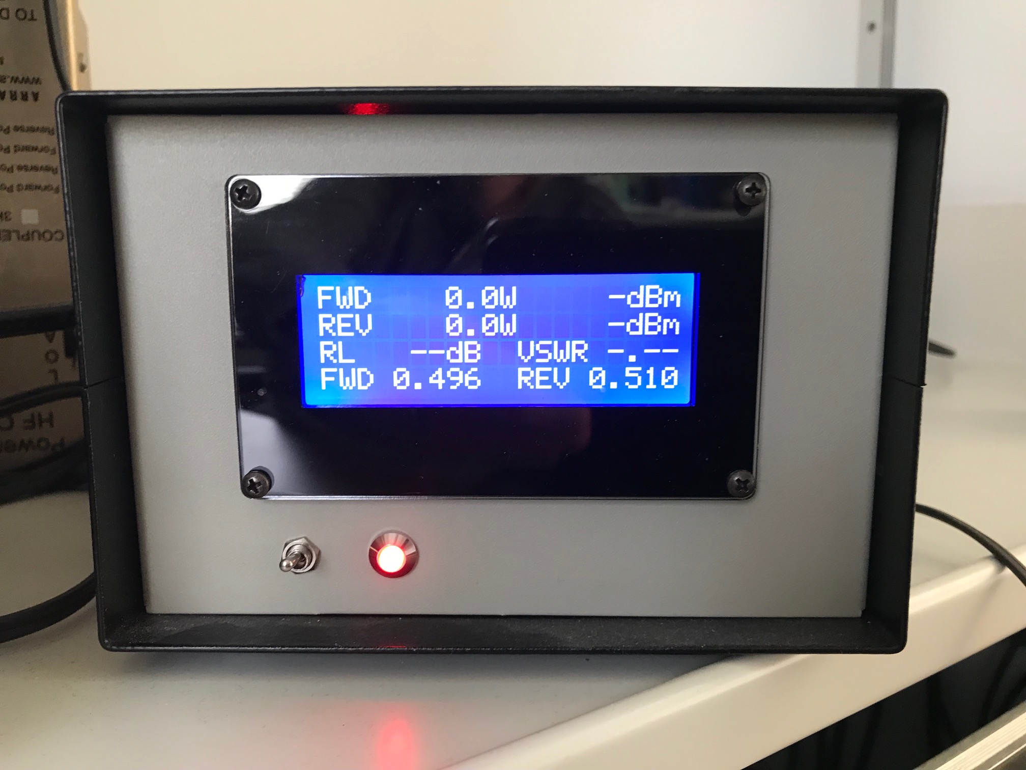
The Arduino sketch is available on my GitHub page https://github.com/nielsm59/rf-power-meter
References
- G4WNC - Practical Wireless Aug 2015
- ON7IR RF Power Meter
- DL2SBA RF Power Meter